G Systems developed an integrated system for Lockheed Martin Aeronautics to use in the F-35 Vehicle Systems Integration Facility (VSIF) to monitor aircraft sub-system integration tests.
G Systems developed an integrated system for Lockheed Martin Aeronautics to use in the F-35 Vehicle Systems Integration Facility (VSIF) to monitor aircraft sub-system integration tests.
Developing an integrated system that can acquire various types of data, including analog, digital, video, and additional data transferred from other systems through reflective memory, for Lockheed Martin Aeronautics to use in the F-35 (also known as the “Iron Bird”) Vehicle Systems Integration Facility (VSIF) that monitors aircraft sub-system integration tests. Requirements included real-time display capabilities and the ability to easily manage all components of the system from transducer setup to data management.
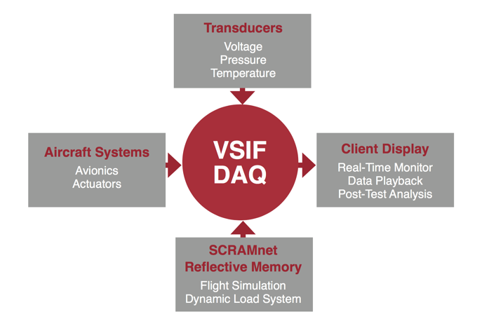
G Systems developed highly flexible software and used off-the-shelf NI hardware and other third-party tools to create a high-channel-count system that exceeded Lockheed Martin’s initial requirements. The expandable nature of the PXI platform enabled us to increase the system’s channel count by 60 percent over the initial system requirements.
Figure 2 shows the general architecture of the VSIF high-channel-count data acquisition system. The
data acquisition system is distributed across several servers to enable load balancing and achieve the required system performance. We built the distributed software architecture, which includes six major custom applications, to allow for future expansion of the system.
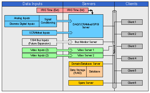
Figure 2: VSIF Data Acquisition System Overview
Analog and digital data acquisition are performed using five PXI chassis populated with a variety of NI DAQ boards for a total of 640 analog channels and 480 digital channels. The ability to mix-and-match different types of DAQ boards while maintaining time synchronization was important for controlling the overall hardware costs of the system. Time synchronization is maintained in the high-channel count distributed system using an IRIG time signal that can be provided by VSIF DAQ or another source within the VSIF lab.
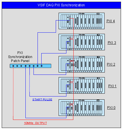
Figure 3: VSIF Data Acquisition System PXI Synchronization
The application that acquires the analog and digital data also performs PXI board verification and internal calibration and signal path calibration using an external DC source controlled by GPIB. Automation of the signal path calibration allows system verification to be performed automatically in just 20 minutes. With previous systems, this type of operation could take several hours and required significant operator interaction.
All data is delivered to the end-user in engineering units (EU) and takes into account the calibration values for the A/D, the signal conditioning module, the transducer, and zero nulling values where appropriate. Derived channels, which are channels that are calculated from information contained in other channels, such as Watts=Volts*Amps, can be calculated as well. Additionally, there are built-in interface-to-link user-defined external DLLs in the system that don’t require the software to be recompiled to create more complex derived channels.
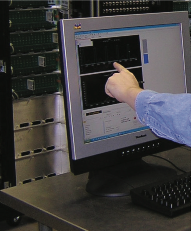
Figure 4: Engineers Using the Highly Configurable Data Acquisition System Software
The configuration information for the VSIF data acquisition system is stored in a relational database. We developed a custom graphical user interface (GUI) that system administrators use to configure every aspect of the data acquisition system, including the following:
1. User Management
2. Hardware Inventory
3. System Configuration
4. Data Administration
5. Reporting
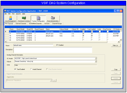
Figure 5: VSIF DAQ System Configuration Editor
The application is designed to help system administrators easily handle the system’s high channel count by providing capabilities such as column sorting and filtering, channel group definitions, multi-record editing, and copy/paste functionality. Through user permissions, any user can view the system configuration, but only authorized administrators can change values. Several administrator permission levels are provided to allow precise definition of privileges for an individual user.
Since many different user groups test various aircraft sub-systems during integration tests, a single static user display was not a good solution for the VSIF data acquisition system. Instead, we created a dynamic user-configurable data display application that allows any user to create custom views of data with several indicator choices available.
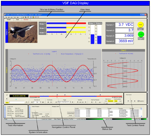
Figure 6: VSIF Data Acquisition System Data Display GUI
This application supports advanced navigation functions allowing users to instantly review data in real time or to recall and view logged data from previous test runs. Users can set triggers and alarms to quickly find points of interest in data.
The system stores all information for an individual user configuration in the database, which can be exported along with test data for standalone review or playback. This makes it possible for a user to take a snapshot of test data, including all calibration and transducer information from several test runs, and use it independently of the main VSIF data acquisition system database, which can be useful for offline analysis or presentation.
The test control/monitoring/playback application shown in Figure 6 provides several modes of operation for the user. The system constantly acquires data and publishes it in a “low-res” format to six client workstations. As the published data set is received, it is buffered continuously on the local client in a 30-minute rolling buffer. From this buffer, a user can look back in time at data that was published or logged and replay it in real time if desired.
When the operator chooses to log data, the “high- res” data is logged to file and later transferred
to a central repository. These test runs can be downloaded to a workstation for detailed review of the data in the playback mode. The user can playback the data in real time or can navigate through the logged data timeline using several navigation options.
All logged data is controlled and protected in the VSIF data acquisition system. The data is automatically moved from the acquisition servers to a central data storage unit (RAID) when a user starts logging a test run. Users can review the test data but are prohibited from deleting any test data from the RAID. Both the data display and data analysis export application can directly call up data that exists either on the RAID or in an archived dataset. This allows relatively unskilled users to easily review previously logged data with a minimal amount of VSIF-specific training.
The VSIF data acquisition system provides advanced analysis capabilities through a custom DIAdem data interface (DDI) application that exports data to the DIAdem analysis package or to simple ASCII text files. The DDI leverages all of the database interface and EU conversion functionality developed for the data display application to feed data directly into DIAdem through an OLE interface. The application is structured to allow the operator to easily select the test run(s) and channel(s) to export to DIAdem and supports merging of data from several test runs.
“G Systems provided Lockheed Martin Aeronautics with a highly-configurable, expandable, high-channel-count system to meet current and future requirements of the F-35 Vehicle Systems Integration Facility.”

Through the use of an advanced software architecture and reconfigurable, flexible hardware,
G Systems provided Lockheed Martin Aeronautics with a highly-configurable, expandable, high-channel-count system to meet current and future requirements of the F-35 Vehicle Systems Integration Facility.
After nearly 15 years of running the data acquisition system 24/7, the system is still reliably functioning. But, as with any hardware/software system, it sometimes needs upgrades to avoid obsolescence. Since we designed the VSIF data acquisition system using off-the-shelf technology rather than propriety technology, the upgrades have been a smooth process for Lockheed Martin.
The best way to begin is by having a conversation with a member of the G Systems teams about your test challenges and the options for helping you solve them.