The process of making accurate measurements in an RF test component system includes many variables as mistakes in the measurement process can cause inaccurate readings that devastate the overall testing processes. Here are five mistakes you may be making in your RF test measurements and key considerations to ensure your RF measurements are as accurate as possible:
1. Your RF Test Measurements Aren’t Actually Repeatable
The first key to accurate measurements is ensuring you can make repeatable measurements. If you don’t constrain outside variables appropriately, your measurements will be indefinitely inaccurate.
To make repeatable measurements, keep the following in mind:
- Know the correct measurements for your connectors and torque – brass connectors often have lower torque specifications than those made of stainless steel.
- Use the proper tools for your measurements.
- Test your measurements with varying amount of settling time or averaging.
- Anticipate the level and associated signal noise you’re going to measure – you can expect a higher signal-to-noise ratio with lower amplitude signals.
2. You’re Making Too Many Absolute Measurements
If given the chance, make relative RF measurements instead of time-consuming absolute RF measurements. Sometimes you can completely avoid characterizing your test setup by making only relative RF test measurements.
To achieve relative measurements:
- Consider using something resembling the following set up – connect the measurement system without an amplifier and record the frequency of system response, then insert an amplifier into the test system and re-measure the frequency response. Subtract the first measurement from the second to obtain the amplifier measurement, and the result is a relative measurement.
- Ideally, use the same number of adapters in both measurements to achieve the same insertion loss and response vs. frequency.
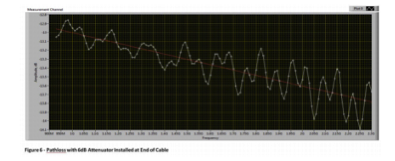
3. You Haven’t Characterized Pathloss Correctly
Sometimes, you need to make absolute measurements of an RF signal instead of relative measurements. In this case, it is important to know the loss of any RF components between the signal of interest and your measuring instrument. These loss sources might include any number of RF relays, interconnecting cables, attenuators, and adapters. Pathloss contributions must be carefully characterized because they become part of every subsequent measurement in a one-to-one proportion.
To carefully characterize pathloss in in applications, consider the following:
- To calculate pathloss for measuring instruments such as a power meter or vector signal analyzer, establish an accurate reference level at the point of measurement and take the measurement with your instrument. Doing the math will give you the pathloss between your reference point and the measuring instrument.
- The process of calibrating measurement pathloss takes twice as long as the process for stimulus pathloss because you must make twice as many measurements, which also leaves more room for error. Keep any cabling as stationary as possible to prevent changes in reference power during the two runs, and try to minimize any additions or subtractions of adapters between the reference run and the final run.
4. Crosstalk is Ruining Your Measurement Readings
Good isolation inside your RF test system is important for quality measurements. When dealing with sensitive measurements like phase noise, it doesn’t take much crosstalk to ruin your reading.
To ensure accurate readings and preserve isolation:
- Ensure you have quality RF cables with shielding effectiveness specified on a datasheet.
- For good shielding that improves isolation, consider a foil-wrapped and braided or double-shielded outer braid coax cable — semi-rigid coaxial cables achieve the best isolation but are less flexible than others.
- Choose the appropriate RF relay based on isolation between open terminals at the frequency of interest.
- Consider the lifetime of your RF switch – the mechanical and electrical lifetimes specified for the switches should exceed the requirements of your application.
- Remember that everywhere there is an RF adapter, there is a chance for signal leakage.
- Keep the same connectors throughout your RF test system to reduce the need for adapters, and when adapters are necessary, use high quality ones.
5. Reflections Impede Your Measurements
High Standing Wave Ratio (SWR), caused by high reflectivity (Γ) are a frequent cause for inaccurate measurements. Reflections are caused by mismatches from the primary impedance (Z0=50 ohms) of various system components such as adapters, attenuators, splitters, cables, and connectors.
Consider the following to manage return loss and reflections:
- Two of the more popular impedances for RF components are 50 ohms and 75 ohms
- Impedance mismatches can take place when the ATE is initially connected the UUT, but may only become visible when the UUT data is examined.
- Invest in high quality components in order to minimize the effects of reflections.

In summary, RF test component measurements have extensive variables and many factors can cause inaccurate measurements. For a complete look into all of the considerations surrounding accurate RF test component measurements along with example applications for these best practices, read the full white paper.