Fault Insertion Breakout Box
Hardware-in-the-Loop Fault Insertion Box for Electronic Testing
The G Systems Hardware-in-the-loop Fault Insertion Box (HFIB) is used to create signal faults between an electronic control unit (ECU) and the rest of the application’s system to characterize, test, or validate ECU behavior under specific failure conditions. This can be done without interrupting or compromising the operation of the overall system. The G Systems box can change/simulate one or all signal paths between two sources. The test process typically duplicates various conditions which could occur because of corrosion, short/open circuits and other electrical failures through age, damage, or even poor installation. Some examples include ECUs for vehicles, aircraft, spacecraft, and machinery.
Benefits
Allows for embedded firmware-controlled switching between the actual devices and hardware in the loop simulated devices to the unit under test
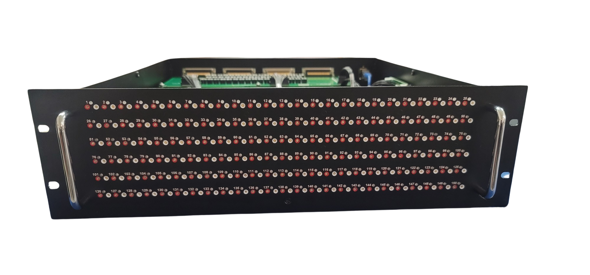
Visual indication of switch state on the front panel
Accessible DMM friendly physical test points on the front panel
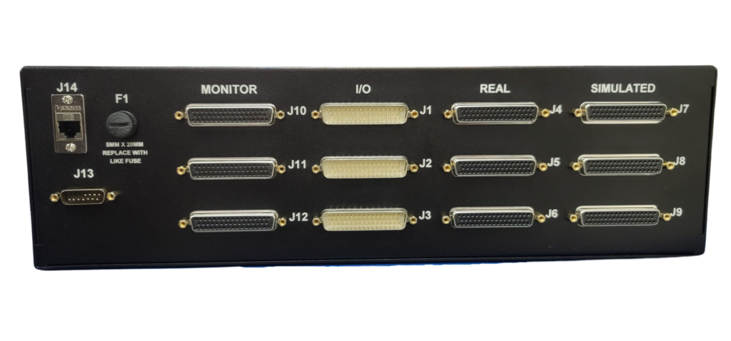
Rear external connector for monitoring signals that are routed to the unit under test
Customizable to meet the customer’s specific test needs
Software Features
Generic D-Sub connectors for all signal connectors
Tip jacks for monitoring signals with a DMM or external device
LED indication of current signal path
Can be built with either shielded or un-shielded or a mixture of both relay types
Customization Options
Optional quantity of signal paths ranging from 50 to 300+
Scalable height dependent on number of signal paths: 1U-5U
Provisioned for a 19” rack but can be easily resized to meet your specific rack widths
The current rack depth is 20.55”, but can easily be reduced by 10” as needed to accommodate different cabling distances inside the rack
Flexible design that includes a Commercially Off The Shelf (COTS) System On Module (SOM) embedded controller that plugs into a separate PCBA that can be easily configured to accommodate any customer specified embedded controller
Case Specifications
Tip Jacks
2mm red tip jacks for monitoring real signals
2mm white tip jacks for monitoring signal routed to the unit under test
Power input
18VDC/3.0A – 30VDC/1.8A; 54W MAX
Reverse Polarity Protection
ESD Protection up to 30kV Air/Contact per IEC-61000-4-2
RS232 Ports
Provides remote communications
ESD Protected up to +/-15kV Air/Contact per IEC-61000-4-2
Ethernet
Provides remote communications and programming of embedded controller
10/100BASE-T with Auto Negotiation and Auto MDI/MDI-X
LED
Bi-color Red (625nm) / Green (562nm)
30mcd Luminous Intensity
40 degrees viewing angle
ESD Protected up to +/- 3kV Air/Contact per IEC-61000-4-2
Test Points / Test Signals
Current Carrying: Up to 1.5A continuous
Relays are rated to up to 1 A max current
Signal Voltage: Up to 200 VDC (as measured between relay COM and NO/NC terminals of the relays)
DC Isolation (between test signals and between test signals and all other circuits): >2kV